The tale of a curious incident, in which I was trying to show how Arduino hinders makers, but was unable to do so because Arduino hindered me!

Some time ago I started a little series of videos* on my YouTube channel, where I show aspiring makers the lesser-known secrets of Arduino and the microcontroller within. The purpose of these videos is to open the viewers’ minds to the options and capabilities that exist outside the gilded cage which is Arduino.
*These specific videos are in Hebrew, but I intend to make English versions as well pretty soon.
To make the second video, whose topic I will not reveal here, I thought it would be nice to utilize the difference between the Reset kinds of the Arduino. Many microcontrollers, the ATmega328P included, have a special register that can tell us what caused the chip to reset. Was it simply because we connected it to power and it started working? Maybe someone pressed the Reset switch on the board? Did the Watchdog module time out? Or perhaps the systems’ voltage dropped below the safe threshold and the Brown-out detector kicked in? In some cases this information is extremely important, so we have MCUSR:

The top four bits are not used. Each of the four bottom bits can get the value “1” if the corresponding kind of reset occurred. For instance, WDRF is a “Flag” that represents a Watchdog Reset. Another important detail that’s mentioned in the Datasheet is that bits 1, 2 & 3 are cleared (become “0”) only when there’s a Power-On reset, or if we write an explicit command to clear them in our code. Otherwise, the “1” values are maintained and we can therefore have a situation where several of these bits are “1” at the same time.
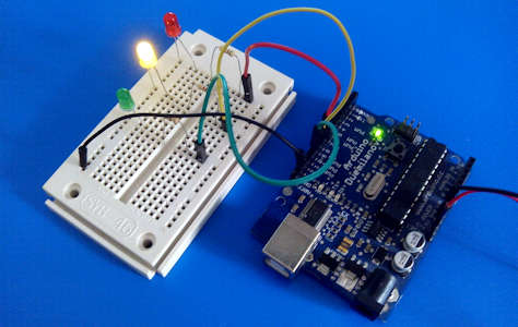
So, as a preparation for my video, I grabbed the nearest Arduino board – it happened to be an old Duemilanove model – connected it to three LEDs and wrote some simple code in the setup function. The code checked the MCUSR register and turned on LEDs according to the bits: red for Power-On (PORF), yellow for Brown-out (BORF) and green for external reset (EXTRF), such as when one presses the “Reset” switch on the Arduino board. I ignored the Watchdog reset for the time being.
It’s also important to mention that my code checked the bits in a series of if…else statements, and cleared a bit immediately after using it. I got the expected red light when I connected the system to power, but when I pressed the Reset switch once, the yellow turned on instead of the green! Only on subsequent presses did I get the green lights. The proper thing to do, of course, would have been to check whether there was an actual brown-out condition on the microcontroller, but due to lazinessforesight I reached a bit farther and grabbed what turned out to be an Arduino Uno. I put it instead of the Duemilanove, turned on the power and… no lights at all.
It was not a hardware problem. After verifying that, I turned to Google and – since I knew what I was looking for – found the answer quickly: it turns out that the Unos’ Bootloader clears MCUSR! It was a lucky coincidence that I picked the Duemilanove first, with its more forgiving bootloader, and could read the reset flags.
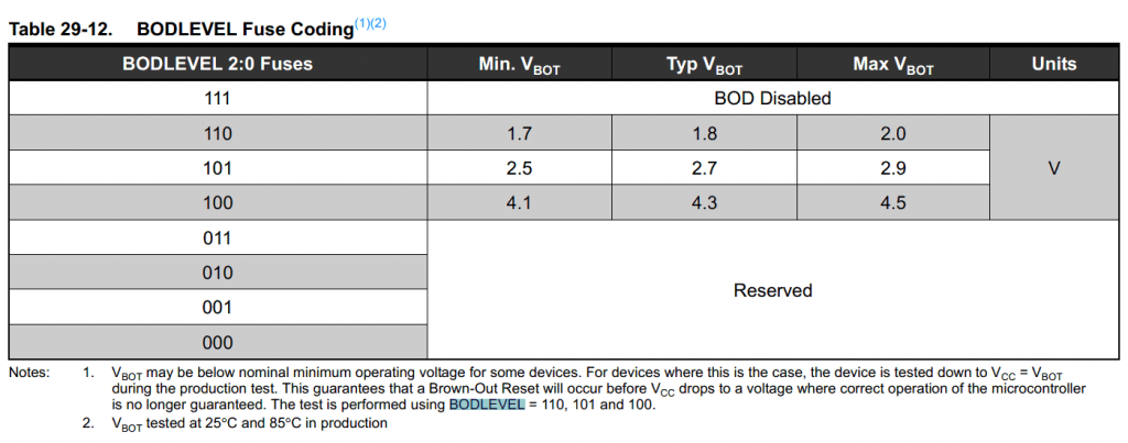
Given that most people don’t have Duemilanove boards, I had to give up that aspect of my video. However, the mysterious Brown-out was still unsolved. So I re-connected the Duemilanove, gave it power directly from my cheap lab power supply and started playing with the voltage. At about 2.6V the microcontroller stopped working, and at 2.8V it woke up again and activated the yellow LED. Brown-out confirmed. By the way, these numbers are not coincidental; that’s the Brown-out threshold that’s defined in the Arduino Fuse settings.

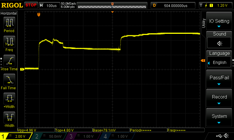
Now I turned on my scope, put the probe directly on the microcontrollers’ Vcc pin and gave the system 5V:

Look carefully: the ~400uS “dip” is just below the Brown-out threshold, so there’s a Brown-out reset immediately after the Power-on reset. I didn’t check yet whether the problem is in my power supply or the Arduino board, but either way that explains the mystery: my code checked PORF first, saw there was a Power-on reset and turned the red LED on. At that time the BORF bit was already “1” as well, but the if..else structure prevented my code from detecting it. It was only seen, acted upon and cleared after the next (manual) reset, when PORF was clear and didn’t take precedence.
So if you have a modern Arduino, the useful information in MCUSR is simply blocked from you. Messing with the bootloader is not recommended for various reasons. A good enough reason to consider switching to stand-alone microcontrollers, don’t you think ? 😉
One last thing, though: why is the Uno bootloader clearing MCUSR? Well, it turns out that this bootloader (“Optiboot”) reads MCUSR to find out the reset source, and may also activate the Watchdog, in order to pass control to the “actual” Arduino code as fast as possible under the circumstances. This means that the contents of MCUSR may change between the “original” reset and the time our own code begins to run, so there’s really no point in saving the data.

A more recent version of Optiboot (6.6 or later?) is able to preserve the MCU reset flags.
My Arduino Uno clone came preloaded with Optiboot 4.x but that does not have the MCU reset flag preserving feature.
I had to get two Arduino boards an use one as the ISP (programmer) to upgrade the target board to Optiboot 6.6
In the global declaration space I then needed to add this cryptic code that invokes some assembler to store the reset flags in a global variable ‘resetFlags’:
// This requires Optiboot 6.6 or later
uint8_t resetFlags __attribute__ ((section(“.noinit”)));
void resetFlagsInit(void) __attribute__ ((naked)) __attribute__ ((section (“.init0”)));
void resetFlagsInit(void)
{
// save the reset flags passed from the bootloader
__asm__ __volatile__ (“mov %0, r2\n” : “=r” (resetFlags) : );
}
And then I found that I could see a difference in ‘resetFlags’ based on power up vs reset – except this was only working on my “freetronics” Uno clone and not my “duinotech” Uno clone. Apparently there is some issue with a pull up resistor on the reset pin that makes certain Uno always appear to be having a power up even if it was just a board reset button click.
Thanks for the detailed info! This code seems to take the information from SRAM, where the bootloader stored it(?), skipping the automatic zeroing of variable (hence the “.noinit”). Should be interesting to see what exactly happens in the “Duinotech” boards.
My Arduino-compatible bootloader doesn’t use the WDR or modify MCUSR. It also uses only 256 bytes.
http://nerdralph.blogspot.com/2018/05/picoboot-adruino-with-autobaud.html
Interesting work. Is there a way to utilize the bytes saved on a regular ATmega328P for the main code (I understand the smallest boot sector available is 512 bytes), or is a 256-byte code only a tour de force?