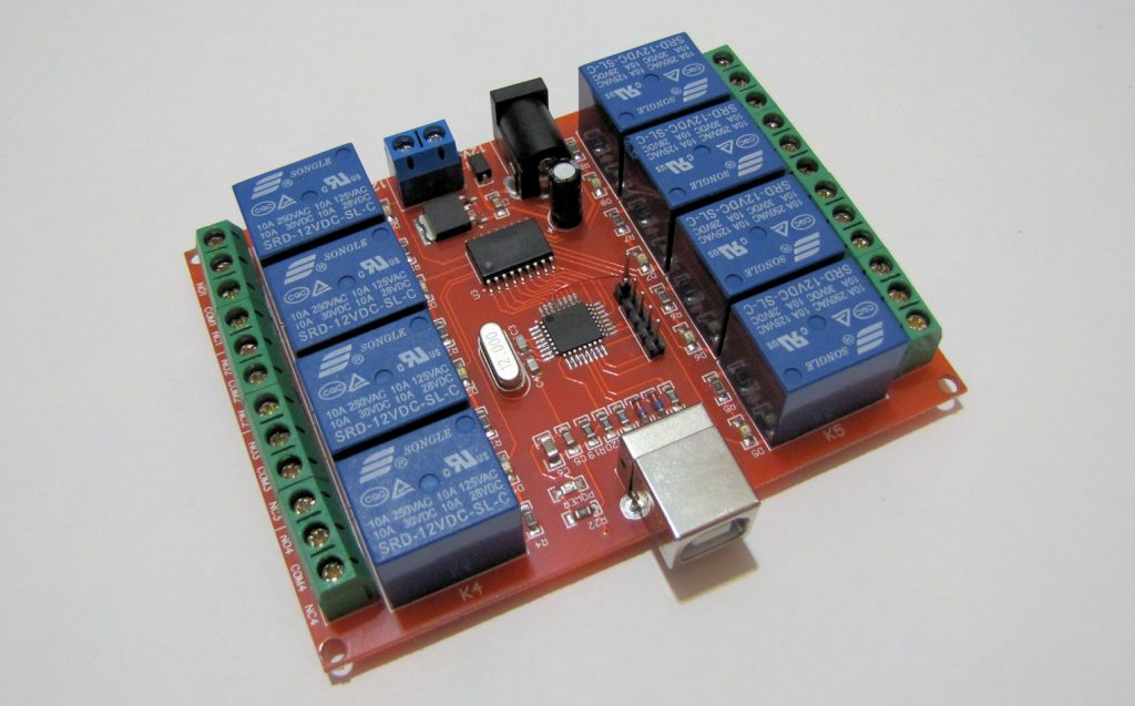
This Chinese “8-Channel USB Relay Board” requires a 12V power supply, and it’s also supposed to plug into the PC for convenient software control. But there was nothing convenient about the software, and I wanted it to work directly with Arduino and other MCUs anyway. Here’s how I replaced the USB interface with a basic UART.

The product page said the board acts as a native USB HID device or something, so there’s no need to install drivers. Excellent. However, there was no link to a software that can actually talk to it. Instead, there was an obscure reference to some DLLs and source codes that I could download to write my own control software with. Well, as much as I enjoy installing shady Chinese DLLs on my system, I thought I’d take a look at other options first.
The board has two major ICs on it: an ULN-thingy to drive the relays, and the venerable ATmega8 with a 12MHz crystal. Obviously, the MCU was programmed to emulate a USB device (the ATmega8 doesn’t have any hardware USB capabilities).

Setting Up The Programmer Interface
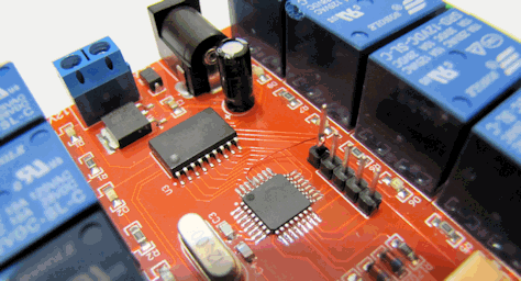
Near the MCU there was a row of four promising, unpopulated holes. With the aid of the ATmega8’s datasheet I traced these back to pins PB2-5, and that made me happy, because these turned out to include the SPI pins (called MISO, MOSI and SCK) through which I can reprogram the MCU. Unfortunately, there was no hole for the RESET pin (PC6) which I also need.
I took a 5-pin male header, and pushed the last pin up through its little plastic holder until it was flush. I soldered the four others to their place, and then soldered a very thin enameled copper wire from the RESET pin of the MCU to the raised header pin. This was neither the easiest nor the prettiest soldering job I’ve ever done, but it was enough to give me the access I needed for the AVR programmer. When the Atmel Studio IDE identified the ATmega8, before anything else I downloaded and backed up the FLASH and EEPROM contents of the MCU, in case I wanted to restore them later. The considerate Chinese did not put any protection there.
Lousiest Software UART Ever
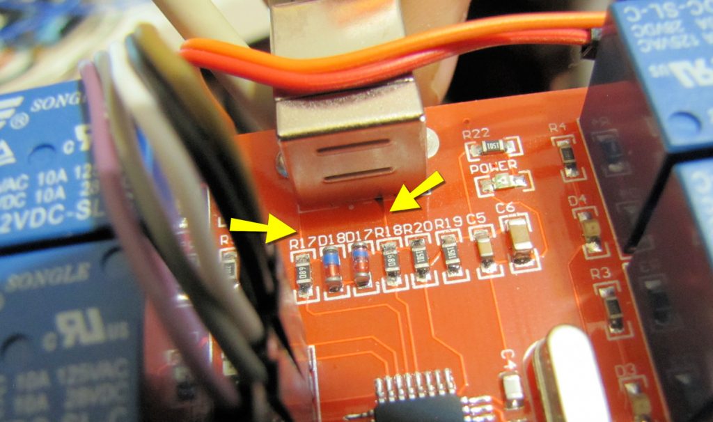
I wanted to be able to control the relays through UART (like the Serial object in Arduino and its associated RX/TX pins). The ATmega8 has a hardware UART module, but unfortunately, its hard-wired pins PD0 and PD1 were occupied by the relays. However, since I was not going to use the USB anyway, I could repurpose the two USB data lines, which were connected to PB0 and PB1, for a software emulated UART. I took an old USB cable, cut it at the middle, then exposed and added convenient jumper-wire headers to its four inner wires.

I wrote a simple C program for the ATmega8 that listens to PB1 (which I chose to be my RX pin). The most common UART transmitters hold the idle line HIGH, and transmit bytes using a “start bit” (a fixed period of LOW), followed by 8 data bits (each the same fixed period, HIGH or LOW, lowest bit first), and finally a “stop bit” (HIGH). Using the very common bitrate of 9600 bits per second, the fixed period of each bit is about 104 microseconds. So my program, as soon as it detects a drop on the line, waits 52+104 microseconds until it’s at the middle of the first data bit, then samples the line eight times with an intermediate delay of 104 microseconds. When it’s done, it distributes the received bits to the proper output pins heading for the relays.
This is a very poor, unsafe way of doing this, but for my test purposes it’s enough. I connected the modified board to an Arduino in continuous reset state (wire from GND to RESET), and through the Serial Monitor managed to send some bytes and see them appear in all their glory as relay states.
A Safer Approach
I said the serial input method was “unsafe”, because it has no way to determine whether the incoming byte is actually a valid transmission at the correct bitrate. To overcome this in the final design, I defined a “protocol” for writing new values to the relays: the sender has to send the character “Z”, then the character “W” (for “Write”), and then the desired byte – all within ~20ms from each other. I chose “Z” because its ASCII code in Binary is 01011010, which has a lower chance of showing up by accident than, say, the character “~” (01111111).
I also added a “read” command (“ZR”). At this, the board will send back on PB0 (“TX”) its current state byte. This can be used to test whether the board is alive at all, and whether it had a power failure that caused it to reset and return to the default state. Of course, I could write the state byte into EEPROM and restore it automatically after reset, but that would be really unsafe… do you see why?

link to download the software
https://www.elecbee.com/en-28711-8CH-Channel-12V-Computer-USB-Control-Switch-Free-Drive-Relay-Module-PC-Intelligent-Controller
[Link edited by admin to remove unnecessary parts]
This is the original software for the pc, of course, not my code or the firmware.
hello can you share the code
This post is 6 years old, I don’t think I have it anymore…
hello, can you share with me your original chinese flash and eeprom files?
Sorry, I didn’t save them…