This is a small note for people who, like me, got confused about the correct pinout of Atmel’s PDI connector.

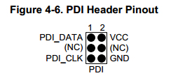
I recently got the new Atmel-ICE Basic programmer/debugger, and immediately wondered about the pinout of the 6-pin PDI connector (PDI being Program and Debug Interface). The Atmel-ICE User Guide has this to say on the matter:

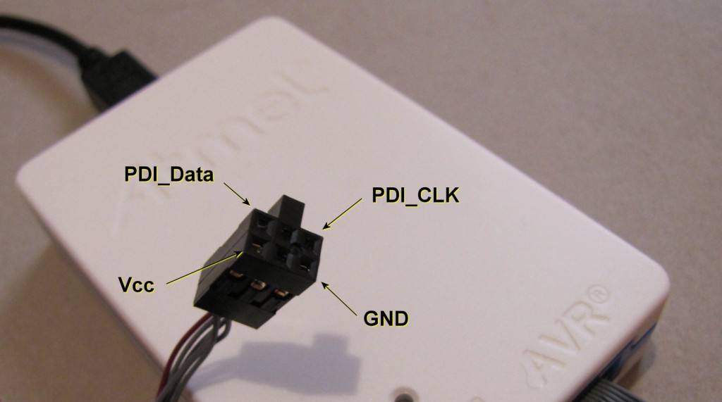
This, as explained in the User Guide’s text, is the board side (i.e. how the connector on the PCB should look like). But looking at the 6-pin connector on the Atmel-ICE side, how can you tell which pin there is number 1? There’s no little arrow, no dot mark to clarify that. The plastic does have a bulge on one side (see top image), but the pinout diagram above does not say which side the bulge should be on…
After searching around, I found an answer through the avrfreaks forums. Looking downward on the PCB, header aligned exactly as in the pin mapping above, the plastic bulge on the connector goes on the left. The image at the top of this post explains exactly what goes where.

Perhaps all this is obvious to professionals, but I hope this post will aid beginners like myself. Let me know in the comments if this helped you in some way!

Holy s**t due thank you! This was confusing the heck out of me, and your info here washed away that confusion in one sweep!
Cool, it’s good to know I’m not the only one who had this problem 😀
You seem to be doing some very interesting stuff yourself!